Co-processor 8087
8087 numeric data processor is also known as Math co-processor, Numeric processor extension and Floating point unit. It was the first math co-processor designed by Intel to pair with 8086/8088 resulting in easier and faster calculation.
Once the instructions are identified by the 8086/8088 processor, then it is allotted to the 8087 co-processor for further execution.
The data types supported by 8087 are −
Binary Integers
Packed decimal numbers
Real numbers
Temporary real format
The most prominent features of 8087 numeric data processor are as follows −
It supports data of type integer, float, and real types ranging from 2-10 bytes.
The processing speed is so high that it can calculate multiplication of two 64-bits real numbers in ~27 µs and can also calculate square-root in ~35 µs.
It follows IEEE floating point standards.
- 8087 Architecture
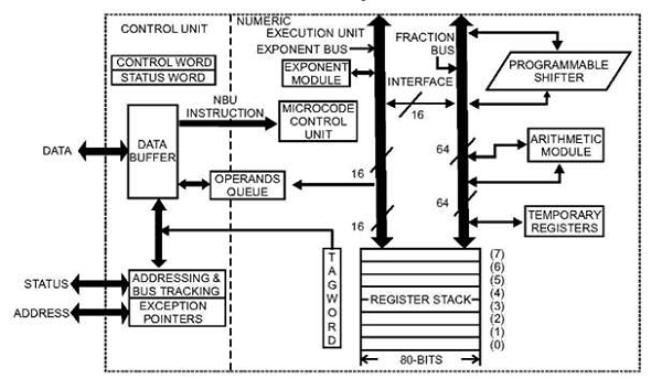
8087 Architecture is divided into two groups, i.e., Control Unit (CU) and Numeric Extension Unit (NEU).
The control unit handles all the communication between the processor and the memory such as it receives and decodes instructions, reads and writes memory operands, maintains parallel queue, etc. All the co-processor instructions are ESC instructions, i.e., they start with ‘F’, the co-processor only executes the ESC instructions while other instructions are executed by the microprocessor.
The numeric extension unit handles all the numeric processor instructions like arithmetic, logical, transcendental, and data transfer instructions. It has 8 register stack, which holds the operands for instructions and their results.
The architecture of 8087 co- processor is as follows −
8087 Pin Description
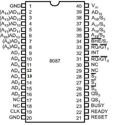
Let us first take a look at the pin diagram of 8087 –
The following list provides the Pin Description of 8087 −
AD0 – AD15 − These are the time multiplexed address/data lines, which carry addresses during the first clock cycle and data from the second clock cycle onwards.
A19 / S6 – A16/S − These lines are the time multiplexed address/status lines. It functions in a similar way to the corresponding pins of 8086. The S6, S4 and S3 are permanently high, while the S5 is permanently low.
BHE¯/S7 − During the first clock cycle, the BHE¯/S7 is used to enable data on to the higher byte of the 8086 data bus and after that works as status line S7.
QS1, QS0 − These are queue status input signals which provides the status of instruction queue, their conditions as shown in the following table −
QS0 QS1 Status
0 0 No operation
0 1 First byte of opcode from the queue
1 0 Empty the queue
1 1 Subsequent byte from the queue
INT − It is an interrupt signal, which changes to high when an unmasked exception has been received during the execution.
BUSY − It is an output signal, when it is high it indicates a busy state to the CPU.
READY − It is an input signal used to inform the coprocessor whether the bus is ready to receive data or not.
RESET − It is an input signal used to reject the internal activities of the coprocessor and prepare it for further execution whenever required by the CPU.
CLK − The CLK input provides the basic timings for the processor operation.
VCC − It is a power supply signal, which requires +5V supply for the operation of the circuit.
S0, S1, S2 − These are the status signals that provide the status of the operation which is used by the Bus Controller 8087 to generate memory and I/O control signals. These signals are active during the fourth clock cycle.
S2 S1 S0 Queue Status
0 X X Unused
1 0 0 Unused
1 0 1 Memory read
1 1 0 Memory write
1 1 1 Passive
RQ/GT1 & RQ/GT0 − These are the Request/Grant signals used by the 8087 processors to gain control of the bus from the host processor 8086/8088 for operand transfers.
Interfacing of 8086 with 8087:
DIAGRAM

1. As a coprocessor (8087) is connected to 8086, 8086 operates in maximum mode. Thus the MN/MX¯MN/MX¯ is grounded.
2. 8284 provides the common CLK, RESET and READY signals. 8282 are used to latch the address. 8286 are used as data trans-receivers. 8288 generates control signals using S2¯¯¯¯¯,S1¯¯¯¯¯ and S0¯¯¯¯¯S2¯,S1¯ and S0¯ as input from the currently active processor. 8259 PIC is used to accept the interrupt from 8087 and send it to the microprocessor.
3. This interface is also called as coprocessor configuration. Here 8086 is called as the host and 8087 as coprocessor as it cannot operate all by itself.
4. We write a homogeneous program which contains both 8086 as well as 8087 instructions.
5. Only 8086 can fetch instructions but these instructions also enter 8087. 8087 treats 8086 instructions as NOP.
6. ESC is used as a prefix for 8087 instructions. When as instruction with ESC prefix (5 MSB bits as 11011) is encountered, 8087 is activated.
7. The ESC instruction is decoded by both 8086 and 8087.
8. If the 8087 instruction has only an opcode (no operands) then 8087 will start execution and 8086 will immediately move its next instruction.
9. But if the instruction requires a memory operand, then 8086 will have to fetch the first word of the operand as 8087 cannot calculate the physical address. This word will be captured by 8087. Now the remaining words (for a large operand) can be fetched by 8087 by simply incrementing the address of the first word. Thus 8087 need help from 8086.
10. Once 8087 gets its operand, it begins processing by making the BUSY output high. This BUSY output is connected to the TEST input of the microprocessor. Now 8087 execute its instruction and 8086 moves ahead with its next instruction. Hence multiprocessing takes place.
11. During execution, if 8087 needs to read/ write more words from the memory, then it does so by stealing bus cycles from the microprocessor in the following manner.
The RQ¯¯¯¯¯¯¯¯/GT0¯¯¯¯¯¯¯¯¯RQ¯/GT0¯ of 8087 is connected to RQ¯¯¯¯¯¯¯¯/GT0¯¯¯¯¯¯¯¯¯RQ¯/GT0¯ of the microprocessor. 8087 gives an active low request pulse. 8086 completes the current bus cycle and gives the grant pulse and enters the hold state. 8087 uses the shared system bus to perform the data transfer with the memory. 8087 gives the release pulse and returns the system bus back to the microprocessor.
12. If 8086 requires the result of the 8087 operation, it first executes the WAIT instruction. WAIT makes the microprocessor check the TEST pin. If the TEST pin is high (8087 is BUSY), then the microprocessor enters WAIT state. It comes out of it only when TEST is low (8087 has finished its execution). Thus 8086 get the correct result of an 8087 operation.
13. During the execution if an exception occurs, which is unmasked, 8087 interrupts microprocessor using the INT output pin through the PIC 8259.
14. The QS0QS0 and QS1QS1 lines are used by 8087 to monitor the queue of 8086. 8087 needs to know when 8086 will decode the ESC instruction so it synchronizes its queue with 8086 using QS0QS0 and QS1QS1 as follows:
QS1 QS0 8087 operation
0 0 NOP
0 1 8087 compares the 5 MSB bits with 11011 (ESC code)
1 0 8087 clears its queue
1 1 If earlier comparison succeeds, 8087 fetches the subsequent byte else NOP
This is the complete inter-processor communication between 8086 and 8087 to form a homogeneous system.
x
x
No comments:
Post a Comment